Parametric Frame Builder
 Used to create parametric
window and door frames. These frames are cells that have both a 3D and 2D (top)
representation (that is, each frame is a compound cell). The 3D appearance of
the cell displays in the 3D model. The 2D appearance is used in the drawings
(horizontal sections) and may display in the 3D model under certain
circumstances. A parametric frame has a 3D representation that is visible in
the 3D model, and a 2D representation that displays in the 2D horizontal
section. A 2D representation of the frame can be displayed in the 3D model by
selecting View Attributes and turning on the Construction attribute.
Used to create parametric
window and door frames. These frames are cells that have both a 3D and 2D (top)
representation (that is, each frame is a compound cell). The 3D appearance of
the cell displays in the 3D model. The 2D appearance is used in the drawings
(horizontal sections) and may display in the 3D model under certain
circumstances. A parametric frame has a 3D representation that is visible in
the 3D model, and a 2D representation that displays in the 2D horizontal
section. A 2D representation of the frame can be displayed in the 3D model by
selecting View Attributes and turning on the Construction attribute.
- Placing frames as shared cells.
- Shared cell frames can be modified individually or globally (all instances in a DGN file).
- Door and window trimming can be added to a frame.
- Forms can be added to the frame to create a push bar, kick and trolley plates, cavity closures and other options.
- A window or door leaf can be divided.
- Openings in a frame can be filled.
| Setting | Description |
|---|---|
| File | The following options are available from the File
menu.
|
| Settings | The following options are available from the
Settings menu.
|
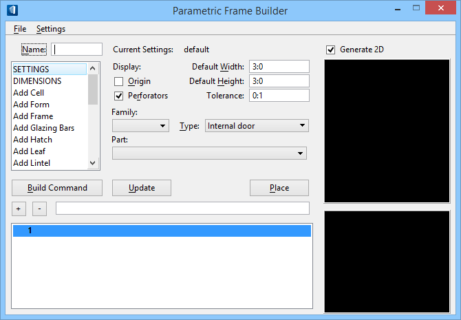
| Name | Used to enter a name for the created cell; displays the name of the cell that is opened. |
| Action list box | Displays a list of Parametric Frame Builder
commands. Each command manages a group of settings that control the creation of
the parametric frame script. The settings group for the selected command is
displayed directly to the right of the Action list box.
The following Parametric Frame Builder commands are
available from the Action list box.
|
| Action list box command settings group | The settings for the selected Parametric Frame Builder command are displayed in the area to the right of the Action list box. Settings in this area change according to the command that is selected. Individual command settings are discussed separately for each command. |
| Build Command | Adds the active entry to the Command list box. |
| Update | Executes the commands in the Command list box. |
| Place | Places the frame as a compound cell into the design file. |
| + button / – button | Entries selected in the Command list box display in the field to the right of these buttons. They are used to insert or delete a command line in the Command list box. |
| Command list box | Displays a list of command lines for the parametric frame script. |
| Generate 2D | When on, generates a 2D portion (cell foot print) and opens a plan view of the parametric frame cell below the front view, on the right side of the dialog. |
| Front View | Displays the model from the front. The XZ plane is parallel to with the screen surface. X is positive from left to right (horizontally), Y is positive from bottom to top (vertically), and Z is positive toward the viewer, or perpendicular to the screen surface. |
| Plan View | Displays the model from the top. The XY plane is parallel with the screen surface. X is positive from left to right (horizontally), Y is positive from bottom to top (vertically), and Z is positive toward the viewer, or perpendicular to the screen surface. |